How to Make MPPT WiFi Solar Charge Controller Circuit Diagram 1kW Arduino MPPT Solar Charge Controller (ESP32 + WiFi): Build a 1kW WiFi MPPT Solar Charge Controller, equipped with phone app datalogging telemetry! (Android & IoS) It is compatible with 80V 30A solar panel setups and all battery chemistries up to 50V. Premium commercial grade MPPTs use the same circuit topology. It turns out, you are not Advantages & Disadvantages of MPPT Solar Charge Controller. The MPPT controller can convert those extra volts into more current, which will charge the battery faster and be much more efficient. Another advantage of MPPT controllers is that they can handle much higher voltage configurations of solar panels to help minimize voltage drop or line

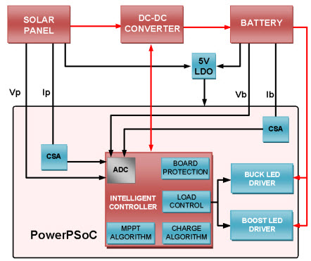
Figure 2 Maximum power point tracking (MPPT) Charge Controller Circuit Diagram The output current of a solar module varies directly with the amount of light (irradiance) as shown in Figure 3a . The maximum power that can be delivered will be greater at a higher irradiance, by reducing the load and maintaining the voltage at a constant level.
Maximum Power Point Tracking (MPPT) Charge Controller Working Principle ... Circuit Diagram
I have a question on Design #1 in your "3 Best MPPT Solar Charge Controller Circuit for Efficient Battery Charging". Under nominal conditions (25 degc, 1000 W / sq m) my solar panel is spec'ed for a Vmp = 19.65v and an Imp = 4.33A. With a 12v battery, will your design develop ~19.65v on the solar panel itself ? This instructable will cover a project build for an Arduino based Solar MPPT charge controller. It has features like LCD display, Led Indication, Wi-Fi data logging and provision for charging different USB devices. Basics on MPPT charge controller. 2. Buck circuit working and design calculation. 3. Testing the Buck Circuit. 4. Voltage and
MPPT solar charge controllers have 2 main circuits, so they basically perform 2 operations: Maximize the power output of the solar array through Maximum Power Point Tracking technology. Decrease the voltage of the solar array to match the voltage of the battery while increasing the current by the same ratio. MPPT Solar Charger Circuit Diagram. The complete Solar Charge Controller Circuit can be found in the image below. You can click on it for a full-page view to get better visibility. The circuit uses LT3652 which is a complete monolithic step-down battery charger that operates over a 4.95V to 32V input voltage range. Thus, the maximum input range The MPPT charge controller circuit diagram is an essential component of any solar panel system, and understanding how it works can help you make the most of your solar energy. From understanding the basics of the circuit to selecting the right charge controller for your particular application, proper installation and use of the MPPT controller